
Simply put, you can understand it as follows:
- The core device is IGBT: IGBT is a composite power semiconductor device that combines the advantages of MOSFET and BJT.
The characteristics of MOSFET: high input impedance (controlled by voltage, low driving power), fast switching speed.
Characteristics of BJTs: Reduced on voltage (low on loss) and strong current carrying capacity.
The result of IGBT: It combines the advantages of voltage control, simple driving, fast switching speed (although slightly slower than MOSFET), low conduction loss, and high current/voltage processing capability. It is particularly suitable for applications with medium to high voltage (above 600V) and medium to high power (several kilowatts to megawatts).
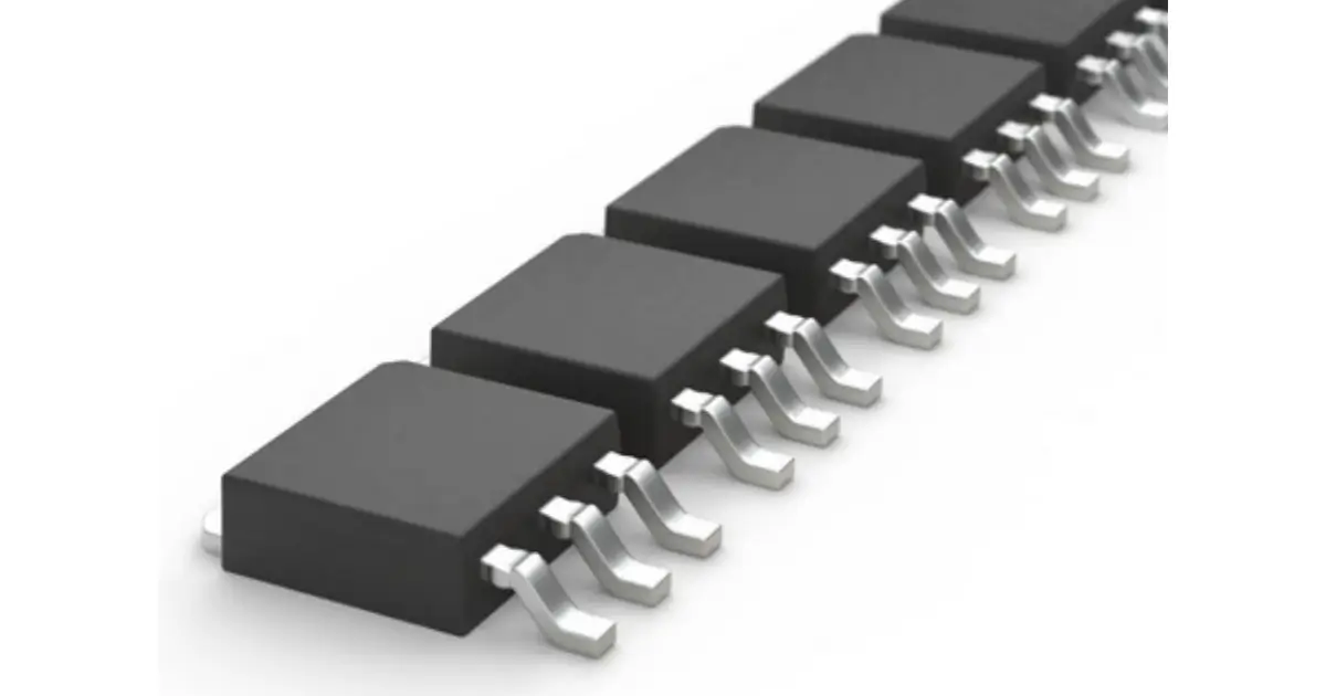
- The meaning of “module”: The power processing capability of a single IGBT chip (referred to as an IGBT die) is limited. To meet the demands of high-power applications:
Parallel chip: Multiple IGBT chips are usually packaged in parallel within a module to increase current capacity.
Integrated anti parallel diode: In practical application circuits such as inverters and frequency converters, IGBT usually requires an anti parallel freewheeling diode. In the module, this diode (usually a fast recovery diode) is directly integrated next to the IGBT chip or connected in parallel using a separate diode chip.
Integrate other components: Some modules also integrate temperature sensors (NTC thermistors), gate resistors, and even driver circuits.

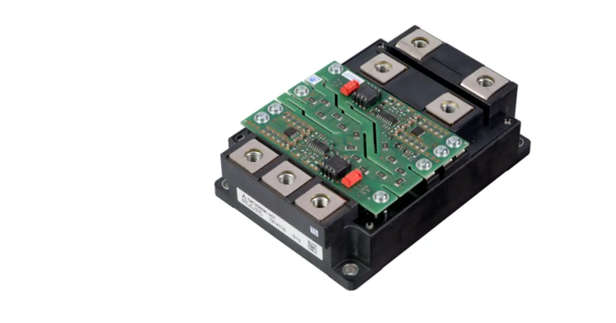
Optimized packaging: The module adopts special packaging techniques (such as crimping and soldering) to provide:
Low thermal resistance pathway: An efficient thermal conduction pathway transfers the heat generated by the chip to the heat sink (usually through thermal grease and metal substrate).
High insulation: Ensure electrical insulation between the high potential of the chip and the heat sink/casing.
Robust electrical connections: high current main terminals (DC+, DC -, AC output) and signal terminals (gate drive G/E, temperature detection).
Mechanical protection and reliability: Protect internal precision chips and connecting wires from environmental influences (dust, moisture, mechanical stress).
Key components of IGBT module:
- IGBT chip: Multiple parallel connections are the main switching components.
- freewheeling diode chip: anti parallel with IGBT chip, providing a freewheeling path for inductive loads.
- DC bus terminal: Connect the positive and negative poles of the DC power supply.
- Communication output terminal: Connect the load (such as a motor).
- Gate drive terminal: receives gate control signals from the drive circuit.
- emitter/auxiliary terminal: used for gate drive circuit and current detection.
- Temperature sensor terminal: Connect the internal temperature detection component (such as NTC).
- Direct bonding of copper substrate: chip soldering or sintering on DBC. DBC is composed of a ceramic insulation layer (commonly Al ₂ O ∝ or AlN) and two upper and lower copper layers, providing electrical insulation and thermal conductivity.
- Metal substrate/baseplate: usually copper or aluminum silicon carbide, used to conduct heat to external heat sinks.
- Shell/plastic enclosure: protects the internal structure, provides mechanical support, and provides a certain degree of environmental sealing.
- Internal bonding wire: Aluminum wire or copper strip connecting the chip to DBC and terminals.
Working principle of IGBT module (brief description):
Conduction: Applying a positive voltage (usually+15V) above the threshold voltage between the gate and emitter forms a conductive channel inside the IGBT, allowing large currents to flow from the collector to the emitter, resulting in a lower voltage drop during conduction.
Turn off: Reduce the gate emitter voltage to 0V or apply a negative voltage (usually -5V to -15V), the conductive channel disappears, and the current is blocked. During the shutdown process, the freewheeling current generated by the load inductance will flow through the anti parallel diode.
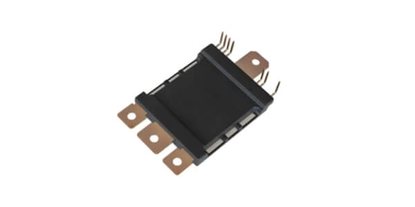
The main advantages of IGBT modules (compared to discrete IGBTs):
- High power density: Integrating multiple chips to achieve high current and high voltage processing capabilities.
- Excellent heat dissipation performance: optimized thermal design and low thermal resistance packaging, suitable for high-power applications.
- High integration: Integrating IGBT, diodes, sensors, etc. into one, simplifying system design and assembly.
- High reliability and lifespan: Industrial grade packaging and testing ensure long-term stable operation in harsh environments.
- Low parasitic inductance: Internal wiring optimization reduces voltage overshoot during the switching process, improving efficiency and reliability.
- Simplified driver: Standardized interfaces and packaging facilitate driver circuit design.
- The main application areas of IGBT modules are:
- Motor drive: industrial frequency converters, servo drives, main drive inverters for electric/hybrid vehicles, electric compressors, etc.
- Renewable energy sources: photovoltaic inverters, wind power converters.
- Industrial power supply: high-power switching power supply, induction heating power supply, welding machine power supply.
- Power transmission: Converter valves and flexible AC transmission system devices in high-voltage direct current transmission.
- Rail transit: traction converters and auxiliary converters for high-speed trains, subways, and trams.
- Household appliances: Variable frequency air conditioners, variable frequency refrigerators, induction cookers.
- Uninterruptible power supply: medium to high power UPS.