描述
Key Features & Specifications
Parameter Specification Notes
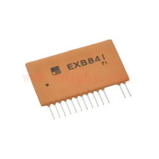
Manufacturer Fuji Electric
Function High-Speed IGBT Driver For IGBTs up to 400A / 1200V
Isolation Optical Isolation, 2500 Vrms Galvanic isolation between input and output.
Supply Voltage (Vcc) +20 VDC (Typical) Single supply operation is a key feature.
Internal Bias Generates ~-5 V Gate Turn-off Bias Created internally from the +20V supply.
Peak Output Current ~4 A Capable of fast switching of medium-power IGBTs.
Integrated Protection Desaturation (Overcurrent) Detection Initiates a soft shutdown upon fault detection.
Propagation Delay tPLH ¡Ö 1.5 ¦Ìs, tPHL ¡Ö 1.4 ¦Ìs Slower and less matched than modern drivers.
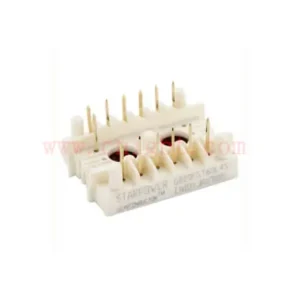
Pin Configuration (14-Pin SIL Package)
Input Side (Control Circuit Side):
Pin 1: LED Cathode (-)
Pin 9: LED Anode (+)
*(Pins 2-7 are typically Not Connected or reserved)*
Output Side (Power Circuit / IGBT Side):
Pin 14: Gate Drive Output (G) -> Connects to the IGBT Gate.
Pin 15: Ground / Emitter Sense (E) -> Must connect directly to IGBT Emitter.
Pin 16: Desaturation Detection Input (C) -> Connects to IGBT Collector via a high-voltage, fast-recovery diode.
Pins 17, 18, 19, 20: Positive Supply Voltage (Vcc, +20V).
Detailed Functional Description
1. Normal Operation:
A positive control signal (typically 10-20 mA) is applied to the internal LED (Pins 9 and 1).
This optically coupled signal is amplified to provide a +15 V gate turn-on voltage (derived from the +20V supply) to the IGBT.
When the input signal is removed, the driver rapidly discharges the IGBT gate to approximately -5 V to ensure a reliable and fast turn-off.
2. Overcurrent Protection (Desaturation Detection):
The EXB841 monitors the voltage between the IGBT’s Collector and Emitter (Vce) via Pin 16.
During normal operation (IGBT saturated), Vce is low (~2-3V). A built-in fast-recovery diode blocks this low voltage.
During an overcurrent or short-circuit fault, the IGBT comes out of saturation and Vce rises sharply.
When this voltage exceeds an internal threshold (typically around 7-8V), the protection circuit is triggered.
Upon detection, the EXB841:
Clamps the IGBT gate voltage to a lower level (~10-12V) to limit the short-circuit current.
Initiates a “soft” or gradual turn-off over several microseconds to reduce di/dt and prevent destructive voltage spikes.
Critical Application Notes & Known Limitations
While functional, the EXB841’s design has several well-documented drawbacks that require careful system design:
Slow Negative Bias Generation: The internal -5V bias is generated at power-up but can be slow to stabilize. Applying a PWM signal before this bias is fully established can cause uncontrolled IGBT turn-on. A power-up delay (e.g., 1-2 ms) in the control signal is mandatory.
Slow and Unmatched Delays: The propagation delays for turn-on and turn-off are relatively long and not perfectly matched. This requires longer dead times in bridge topologies (like half-bridges) to prevent shoot-through, which limits maximum switching frequency.
Limited Negative Turn-off Voltage: The -5V turn-off bias is less robust than the -8V to -15V provided by modern drivers, making the IGBT more susceptible to spurious turn-on caused by Miller effect.
Fixed Blanking Time: The internal circuit has a fixed blanking time to ignore the normal high Vce during turn-on. This blanking time may be too long for modern, faster IGBTs, potentially delaying fault response.
Comparison with Modern Drivers (e.g., Mitsubishi M57962AL)
Feature Fuji EXB841 Mitsubishi M57962AL
Supply Single +20V Dual Supply (e.g., +15V, -10V)
Negative Bias Internal (~-5V) External (more stable and adjustable)
Protection Integrated Desaturation Integrated Desaturation
Performance Slower, legacy design Faster, better-matched delays
Design Advice For legacy repair Recommended for new designs